
Introduction
When you start 3D printing, slicer software throws a lot of new terms at you: infill, layer height, wall loops, supports, line width, and more. Understanding these settings is the first step to getting strong, clean prints that don’t waste time or filament.
Layer height – the “resolution” of your print
What it is
Layer height is the thickness of each printed layer stacked on top of the previous one, for example 0.12 mm, 0.2 mm, or 0.28 mm. It is often called the “vertical resolution” of your print.
How it affects your print
-
Smaller layer height (e.g. 0.1–0.16 mm):
-
Larger layer height (e.g. 0.24–0.3 mm):
Beginner rule of thumb
-
With a 0.4 mm nozzle, start with 0.2 mm layer height for general prints.
-
Stay roughly between 25–75% of your nozzle diameter (for 0.4 mm nozzle, about 0.1–0.3 mm).
Example: Use 0.2 mm for everyday parts, 0.1–0.16 mm for detailed miniatures, and 0.24–0.28 mm when you just need something quickly and don’t care about visible lines.
Line width – how thick each line of plastic is
What it is
Line width (sometimes called extrusion width) is how wide each printed line of filament is, most often slightly wider than your nozzle size.
How it affects your print
-
Wider lines (e.g. 0.45–0.5 mm with a 0.4 mm nozzle):
-
Narrower lines (closer to the nozzle diameter):
-
Finer details but can be more sensitive to under‑extrusion or gaps between lines.
-
Beginner rule of thumb
-
Keep line width around your nozzle diameter or slightly higher (e.g. 0.4–0.48 mm for a 0.4 mm nozzle).
-
Don’t change this until you are comfortable with basic settings.
Walls and wall loops – the outer shell of your model
What they are
Walls (also called perimeters or wall loops) are the outer “shell” lines that define the external and internal surfaces of your model. The slicer prints them before filling the inside.
-
Wall loops = the number of perimeter lines (e.g. 2, 3, or 4 perimeters).
-
Shell thickness = wall loops × line width + top and bottom solid layers.
Why walls matter
-
Most of the strength of a part actually comes from the walls, not just the infill.
-
More wall loops give:
-
Better strength, especially against impacts.
-
Cleaner surfaces and less chance of small holes on vertical faces.
-
-
Too few walls can make parts fragile, even with high infill.
Beginner rule of thumb
-
For functional parts (brackets, tools, mounts), use 3–4 walls plus moderate infill for good strength.
-
Combine wall loops with enough top and bottom layers so surfaces aren’t see‑through (e.g. 4–5 top layers with 0.2 mm layer height).
Example: A phone stand printed with 3 perimeters and 25% infill usually feels stronger than the same stand with 1 perimeter and 60% infill.
Infill – what’s inside the part
What it is
Infill is the internal structure printed inside the outer walls of your part. Instead of being solid, most 3D prints are a shell with a repeating pattern inside that saves material and time.
There are two key infill concepts: infill density and infill pattern.
Infill density
Density is how “full” the inside is, usually set as a percentage.
Trade‑offs
Beginner rule of thumb
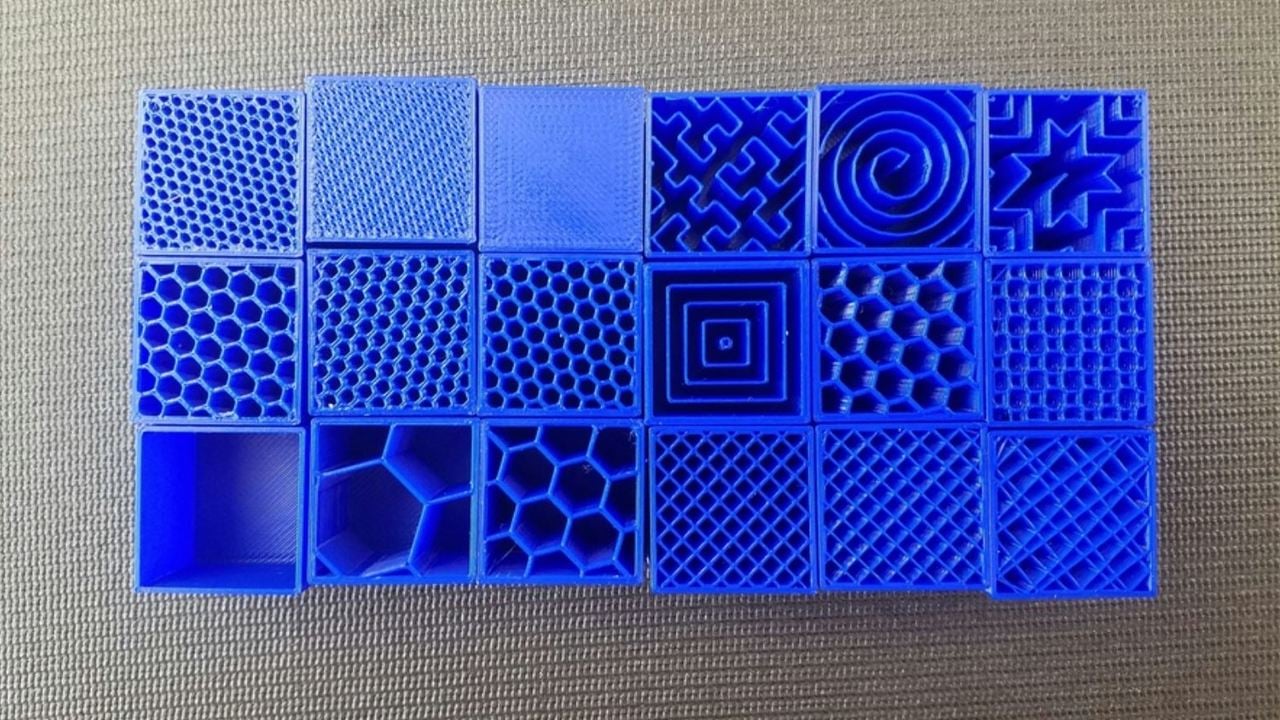
Infill pattern
The infill pattern is the shape of the internal structure: lines, grid, gyroid, honeycomb, triangles, etc.
Here are common patterns and when to use them:
Beginner rule of thumb
Example: A tool holder on the wall can use 3 walls, 25% gyroid infill to resist pulling forces without wasting filament.
Supports – temporary structures for overhangs
What they are
Supports are temporary printed structures that hold up parts of your model that would otherwise be printing “in mid‑air”. After printing, you remove them.
Overhangs and bridges beyond a certain angle need supports because molten plastic sags before it cools.
Key concepts
-
Overhang angle:
-
Support placement:
-
“Touching build plate only” creates supports that start on the bed.
-
“Everywhere” allows supports built on the model itself.
-
-
Support density:
-
Higher density = stronger support and cleaner underside, but harder to remove and slower to print.
-
Lower density = easier removal, rougher underside, less material.
-
Beginner rule of thumb
-
Enable supports only when needed (for steep overhangs, big bridges, or floating features).
-
Use default support density (often 10–20%) and experiment up or down based on removal difficulty.
-
If possible, rotate your model so that fewer areas require support.
Example: A character miniature with an outstretched arm may need supports only under the arm and hand, not under the entire model.
Encourage readers to print a small calibration cube or simple test object and change only one parameter at a time—such as infill density or layer height—so they can clearly see the effect of each setting in real prints.


Leave a comment
This site is protected by hCaptcha and the hCaptcha Privacy Policy and Terms of Service apply.